Here is a quick tutorial on how to create IPSec Site To Site VPN tunnel with Mikrotik RB RouterOS 6.46.1 on both sides.
Before we start, here are a few things to have in mind:
This is the configuration I’m only using in testing environments, not in production. I would recommend creating certificate based IPSec tunnels for production, not ones with pre-shared key (this tutorial is with pre-shared key).
Make sure you have functional routing and configured networks before trying this. You need to be able to communicate normally (ping if enabled on firewall) all public points on future IPSec tunnel.
This configuration is clean configuration, there is no default Mikrotik config preloaded on the routers I’m doing this on.
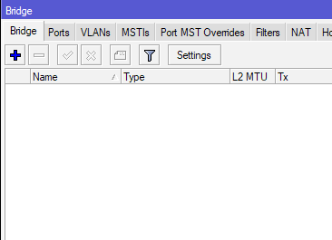
So, I don’t have bridges, or firewalls preloaded, and I only have predefined routes created. Make sure you configure your router safe and secure for production environment, this configuration is just to show in what state can IPSec Site to Site work.
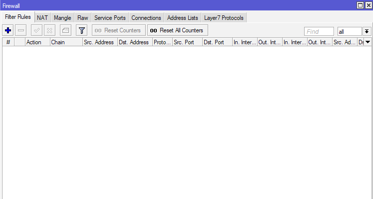
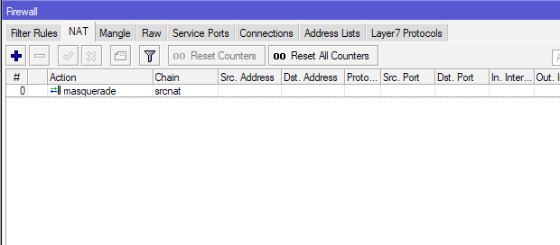
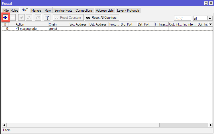
There is only one rule created under Firewall | NAT – on the srcnat chain with masquerade action.
Configuration for this LAB.
Office 1:
Router 1:
WAN IP: 192.168.155.131/24
Default Gateway: 192.168.155.2/24
Local network: 10.50.50.0/24
PC1 : 10.50.50.2/24
Office 2:
Router 25:
WAN IP: 192.168.155.130/24
Default Gateway: 192.168.155.2/24
Local network: 192.168.11.0/24
PC2 : 192.168.11.2/24
So, I will try to connect local subnets from Office 1 (192.168.11.0/24) with local subnet in Office 2 (10.50.50.0/24) via IPSec Site to Site tunnel.
I’m going to show configuration for Office 1 and you should repeat these steps on both side. I will also mention how should settings for Office 2 look like for every step done during tutorial.
I will show how to configure Office 1 router, same steps have to be done on the Office 2 router.
Office 1:
Router 1:
WAN IP: 192.168.155.131/24
Default Gateway: 192.168.155.2/24
Local network: 10.50.50.0/24
PC1 : 10.50.50.2/24
PEERS
First, we will define our Peer. Peer will be router from Office 2 and its public IP address (192.168.155.130).
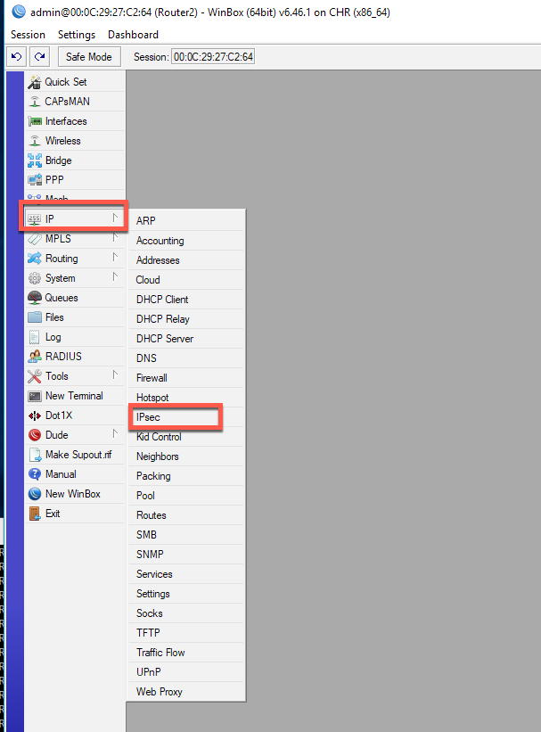
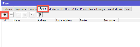
IP | IPSec | tab Peers | click on Plus (+) sign
For a name I will enter Router2 (you enter what best describes your situation) and in Address field I will enter WAN IP address of a Router 2 in Office 2 (192.168.155.130). I will also change Exchange Mode: to IKE2.
The rest will be left as is. Apply OK.
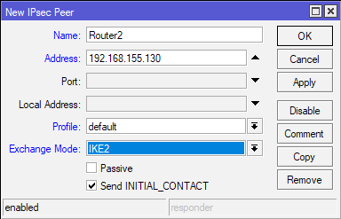
(Office2 – for Office2 this configuration will be – Router1, 192.168.155.131, IKE2)
IDENTITIES
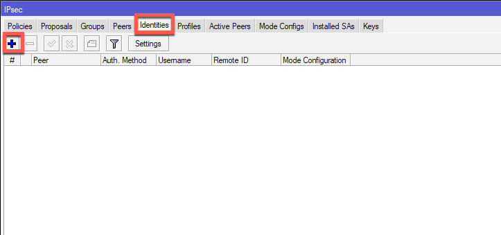
Next stop is Identities tab
IP | IPSec | tab Identities| click on Plus (+) sign
Peer is going to be Router2, Authentication Method – pre shared key, and in Secret field you will enter password. Remember this password, as it is needed on both sides of the tunnel.
Also, if you are using pre shared key in your production IPSec environment, make sure that it is more than 20 signs (letters, numbers, special characters) long.
Leave the rest as default.
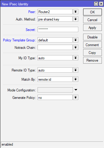
(Office2 – for Office2 this configuration will be – Router1, same Secret as entered in Office 1 on Router 1)
Proposals
Now I’m going to configure Proposals.
IP | IPSec | tab Proposals| click on *default configuration to edit it
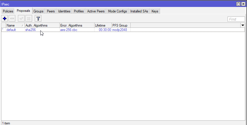
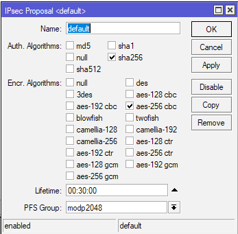
I’m just going to modify default rule for this tutorial. This tab is completely up to you, on how you want to configure it. As Auth. Algorithms I’m going to select sha256, for Encr.Alghorithms aes-256 cbc, lifetime will be 30 minutes and PFS Group modp2048.
Generally, the more secure alghoritms, the better. I would not recommend md5 or sha1 anymore, but will have to decide for yourself. Security should be priority in network communication these days.
Make sure you have the same Proposal configuration on both sides.
(Office2 – for Office2 this configuration has to be the same as the one in Office 1 on Router 1)
Profiles
Again, for this tutorial I will just edit default Profile created.
IP | IPSec | tab Profiles| click on *default configuration to edit it
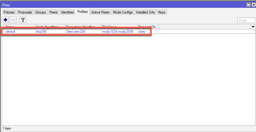
Again, the same rule as for Priorities tab. Select what you see best fit, avoid weak algorithms.
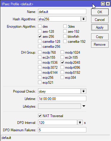
Hash Algorithms: sha256, Encryption Algorithm: aes-256, DH Group: modp2048, Proposal check: obey, lifetime – 1day, NAT Traversal – checked, DPD Maximum Failure 5. Apply – OK.
Make sure you have same settings on both sides.
(Office2 – for Office2 this configuration has to be the same as the one in Office 1 on Router 1)
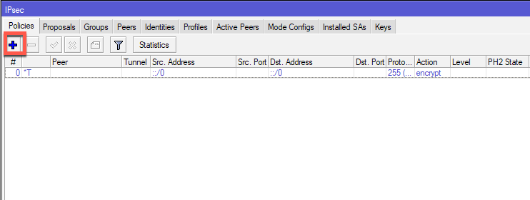
Policies
IP | IPSec | tab Policies| click on Plus (+) sign
On General Tab of the New IPSec Policy, under Peer I will selected created Peer – Router2. I will also check Tunnel, In Src.Address I will enter LAN subnet of local Office1 – 10.50.50.0/24. Under Dst.Address I will enter remote LAN subnet of the remote Office2 – 192.168.11.0/24 and I will leave everything else default.
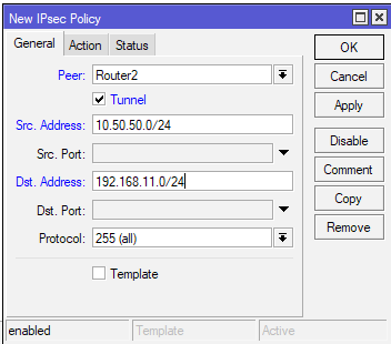
(Office2 – for Office2 this configuration with addresses in different order – Router1, Tunnel checked, Src Address: 192.168.11.0/24, Dst Address 10.50.50.0/24 )
Next in Action tab I will leave everything default.
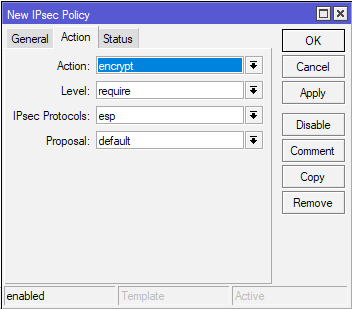
(Office2 – for Office2 this configuration is the same)
Status Tab – there is nothing to change, it is just status of the connection with public IPs from Peer.
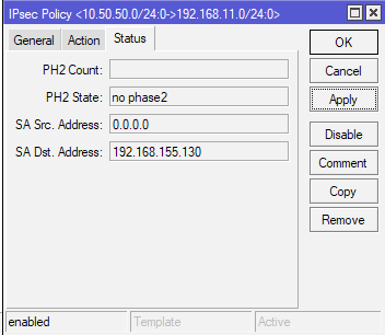
(Office2 – for Office2 this configuration is the same)
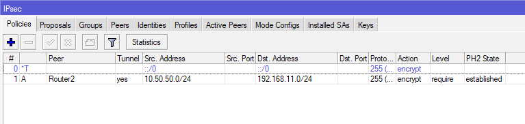
Now, when you finish this same configuration on Office2 (of course with differences in IP settings, as mentioned during tutorial), when you are done with creating policy, you should see this on Policy screen.
Under PH2 State, there should be established state.
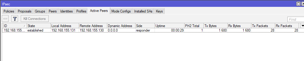
Under Active Peers situation should look like this
And Installed SAs should also be created.
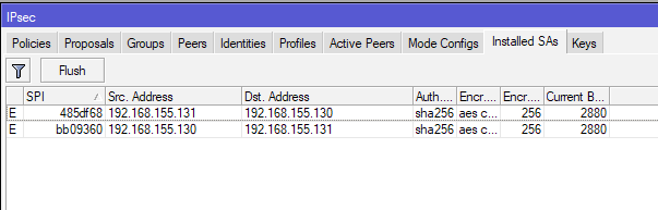
This is what established channel looks like.
Now if you are unable to establish IPSec tunnel, there are a lot of issues that can be reason for this – first, double check all your IPSec settings (Peer, Proposals, Secret, Profile, Policy…)
Check your routing, gateway, NAT and firewall settings (in some case port 500, 4500, 50 and few more needs to go through).
I got a lot of issues with IPSec in the past, and reasons for problems were different, and sometimes very hard to pinpoint.
Now, on local PCs both in Office1 and Office2 I started ping command, but no luck
I started pinging Office1 PC1 10.50.50.2 from Office 2 PC2 192.168.11.1
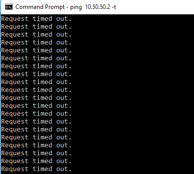
and vice versa
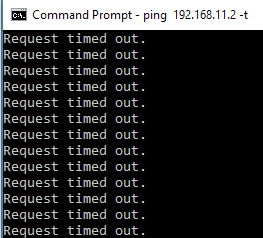
But no luck.
Ok, I allowed ping (ICMP) from firewalls on both machines, but no luck. Tunnel is established, but there is no traffic through it.
Ok, so we need to mess a bit more with routers in both offices.
Again, I’m going to show how to configure Office 1, and steps should be repeated on second side of the tunnel.
IP | Firewall
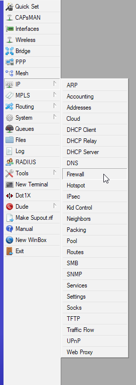
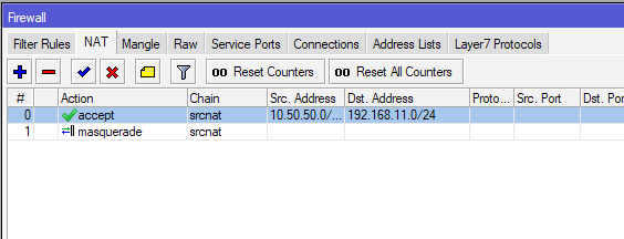
On Firewall select NAT tab and click on plus (+) sign
On New NAT Rule under Chain select srcnat, in Src. Address enter local subnet of Office 1 – 10.50.50.0/24 and in Dst.Address remote subnet of Office 2 – 192.168.11.0/24
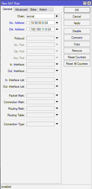
(Office 2 – on Office 2 chain is also srcnat, Src.Address is 192.168.11.0/24 and Dst.Address is 10.50.50.0/24)
Action tab – under Action select Accept. Confirm with Apply – OK
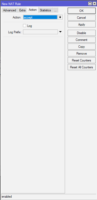
(Office 2 – same setting – accept)
After Rule is created, make sure it resides on the top spot in NAT tab – it is very important that this is the first rule!!
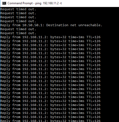
Repeat process on the other side and then REBOOT both routers.
After reboot ping should start
Traffic can also be seen through created NAT rule.
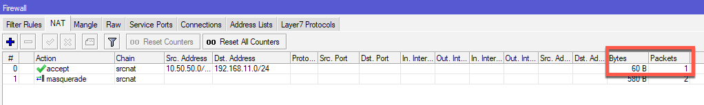
That is it, I have a working IPSec Site to Site tunnel.
This is simple scenario and I have done it in VM. When deploying this in testing environment, make sure you have working public IPs and routes so routers can see each other.